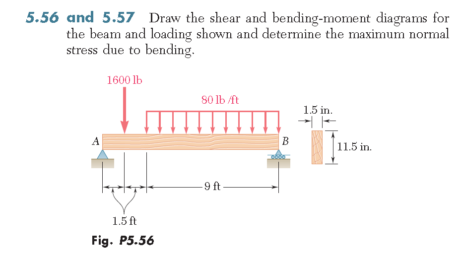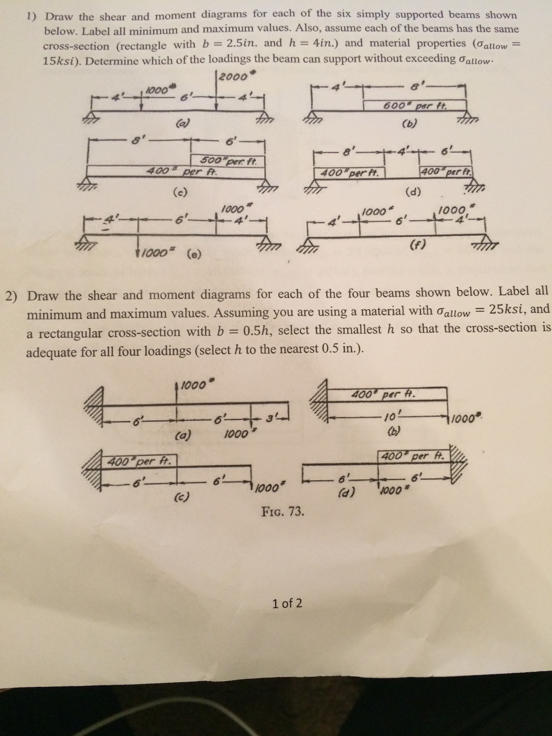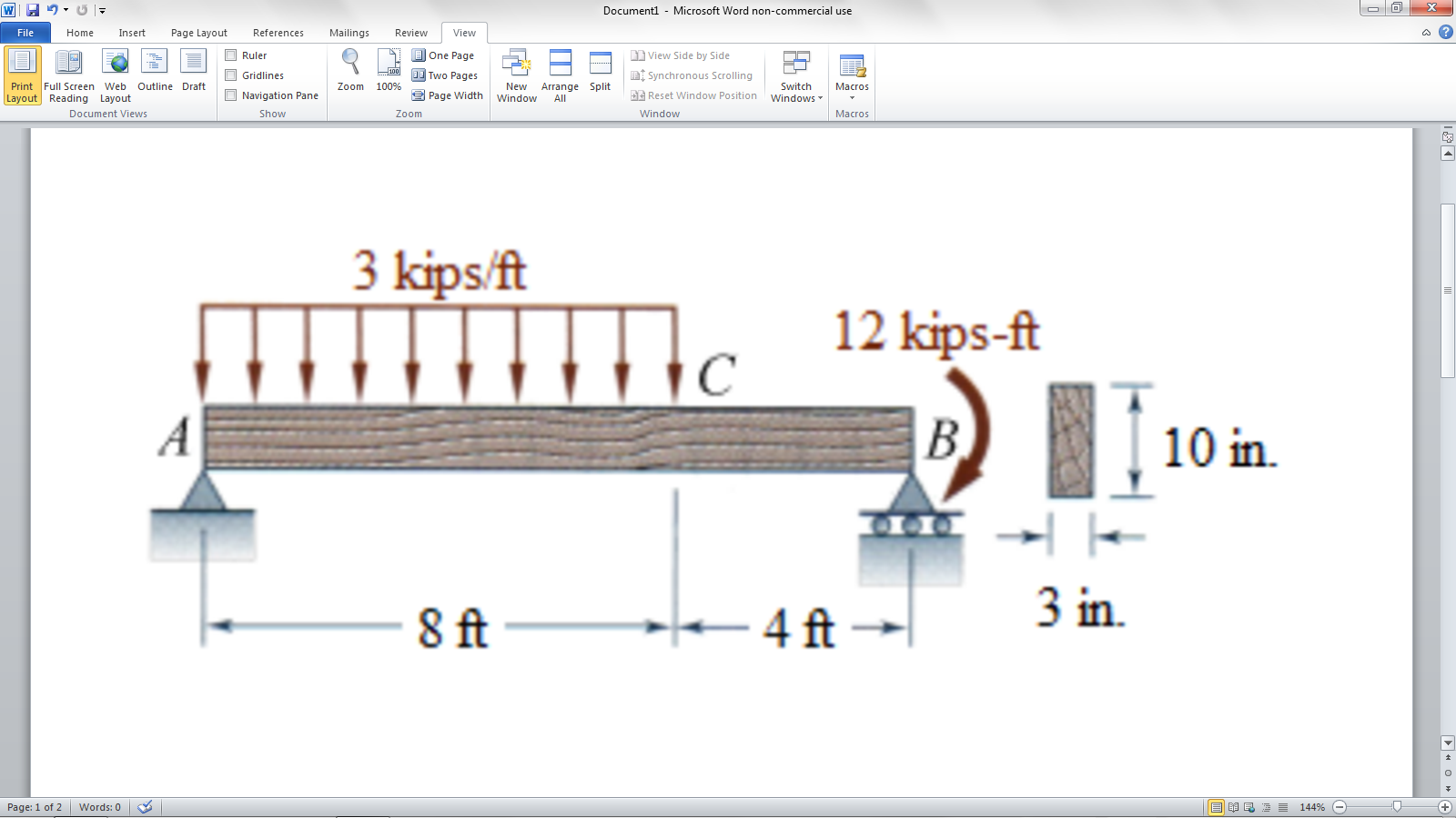

Starting from the unsupported end of the cantilever you would start with zero shear force at the point where you first encounter applied load as you move today the fixed support. In your answer the type of a function is "linear increasing slope" for the function that actually has linear decreasing slope, the answer will be graded as incorrect. Answer: Start with the shear force diagram. Note 2 - Be sure to indicate the correct types of the functions between the lines, e.g. If you inadvertently place two vertical lines at the same place, It will appear correct visually because the lines overlap, but the system will mark It wrong. Label all local maximum and minimum values and their locations and show your sign convention for each diagram. Draw the diagram and the bending moment diagram for the beam. Note 1 - Make sure you place only one vertical line at places that require a vertical line. The beam is and subjected to a linearly varying load from A to B, a point moment at point D a point load at point E as shown. Then click on "add segment" button to add functions between the lines.

Click on "add discontinulty" to add discontinulty lines. M Review Draw the moment diagram for the beam. + 0 6 KNI 8 kN/m 1.5 m 1.5 m No elements selected V, KN 25 20+ 15+ 10+ 5 MacBook Air

Use the button "change segment" if necessary. In your answer the type of a function is "linear increasing slope" for the function that actually has linear decreasing slope, the answer will be graded as incorrect. We will take different cases of beams and loading for plotting S.F. Note 2 - Be sure to indicate the correct types of the functions between the lines, e.g. A bending moment diagram is the graphical representation of the variation of he bending moment along the length of the beam and is abbreviated as B.M.D. If you inadvertently place two vertical lines at the same place, It will appear correct visually because the lines overlap, but the system will mark it wrong. Note 1 - Make sure you place only one vertical line at places that require a vertical line. Click on "add discontinulty" to add discontinuity lines. Part A Draw the shear diagram for the beam. Follow the sign convention Figure < 1 of 1 6 KN 8 kN/m А 1.5 m 1.5 m Transcribed image text: Draw the shear and moment diagrams for the beam in (Figure 1).


 0 kommentar(er)
